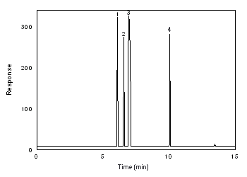
|
1,1-DICHLORO-1-FLUOROETHANE (Freon
141b)
|
| Method number: | 113 | |
| Matrix: | Air | |
| Freon 141b | Freon 113 | |
| Target concentrations: | 1000 ppm | 1000 ppm |
| OSHA PEL: | 1000 ppm (7600 mg/m3) | |
| ACGIH TLV: | 1000 ppm (TWA) (7600
mg/m3) 1250 ppm (STEL) (9580 mg/m3) | |
| Procedure: | Samples are collected by drawing a known volume of air
through two standard size | |
| Recommended air volume and sampling rate: |
1 L at 50 mL/min (20 min) | |
| Freon 141b | Freon 113 | |
| Reliable quantitation limits: | 2.7 ppm (13 mg/m3) | 3.1 ppm (24 mg/m3) |
| Standard error of estimate at the target concentration: |
Freon 141b 5.6% |
Freon 113 5.4% |
| Status of method: | Evaluated method. This method has been subjected to the established evaluation procedures of the Organic Methods Evaluation Branch. | |
| Date: November 1998 | Chemist: Donald Burright | |
Organic Methods Evaluation Branch
OSHA Salt Lake
Technical Center
Salt Lake City, UT 84115-1802
1. General Discussion
- 1.1 Background
- 1.1.1 History
There has been an
assortment of samplers to collect chlorofluorocarbons (Freons). They
include standard charcoal tubes (100/50 mg), Carbosieve
Attempts to desorb the Freons from Anasorb CMS resulted in low
recovery. This was due to the amount of air displaced and heat
generated when the desorbing solvent was added to the vial
containing the absorbent. Several solvents and techniques were tried
with poor results. An aluminum block had holes drilled into it to
fit the desorption vial. One technique that had worked with other
analytes was to cool everything. The block, vials containing
adsorbent, pipettes and desorbing solvent were all cooled to
This method covers only Freon 141b and Freon 113 because all five Freons being studied were not soluble in the same solvent. This procedure uses carbon disulfide to desorb the samples. Freon 12, Freon 22 and Freon 134a are more soluble in a desorbing solution consisting of 60/40 dimethyl formamide/carbon disulfide and will be described in a later method.
1.1.2 Toxic effects (This section is for information only and should not be taken as the basis of OSHA policy.)
Short-term exposure to Freon 113 may cause irritation of the eyes and throat or drowsiness. Breathing high concentrations may cause the heart to beat irregularly or to stop. Prolonged or repeated skin exposure to Freon 113 may cause skin irritation. (Ref. 5.5)
Exposure to Freon 141b may cause dizziness, eye irritation, difficulty in breathing, rapid heartbeat, and low blood pressure. (Ref. 5.6)
1.1.3 Workplace exposure
Freon 113 has been used as a refrigerant, a
heat transfer medium, a solvent for oils and gums, a film processing
solvent, a degreasing and
Freon 141b is one of the new 'environmentally-safe' Freons. It is used as a degreasing solvent and as a blowing agent for refrigerator insulation. The US Clean Air Act mandates the phase out of Freon 141b by 2003 as it also depletes the ozone. (Ref. 5.8)
1.1.4 Physical properties and other descriptive information (Refs. 5.6, 5.7 and 5.9)
| Freon 141b | Freon 113 | |
| CAS number: | 1717-00-6 | 76-13-1 |
| molecular weight: | 116.95 | 187.38 |
| boiling point, °C: | 32 | 48 |
| melting point, °C: | - 103 | - 35 |
| color: | colorless | colorless |
| specific gravity: | 1.25 | 1.57 |
| molecular formula: | C2H3Cl2F | C2Cl3F3 |
| vapor pressure, kPa (mmHg): |
2 (15) | 44 (330) |
| odor: | slight etheral | |
| solubility: | insoluble in water | alcohol; ether; benzene; 0.02% in water |
| synonyms: | Freon 141b; |
Freon 113; |
| structural formulas: | 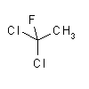 |
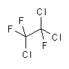 |
The analyte air concentrations throughout this method are based on the
recommended sampling and analytical parameters. Air concentrations listed
in ppm are referenced to
1.2 Limit defining parameters
- 1.2.1 Detection limit of the analytical procedure
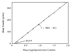
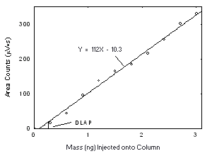
The detection limits of the analytical procedure are 0.12 and 0.26 ng for Freon 141b and Freon 113, respectively. These are the amounts of each analyte that will give a response that is significantly different from the background response of a reagent blank. (Sections 4.1 and 4.2)
1.2.2 Detection limit of the overall procedure
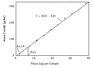
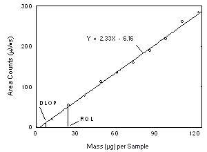
The detection limits of the overall procedure are 4.0 (0.84 ppm or 4.0 mg/m3) and 7.2 (0.94 ppm or 7.2 mg/m3) µg per sample for Freon 141b and Freon 113, respectively. These are the amounts of each analyte spiked on the sampler that will give a response that is significantly different from the background response of a sampler blank. (Sections 4.1 and 4.3)
1.2.3 Reliable quantitation limit
The reliable quantitation limits are 13 (2.7 ppm or 13 mg/m3) and 24 (3.1 ppm or 24 mg/m3) µg per sample for Freon 141b and Freon 113, respectively. These are the amounts of analyte spiked on a sampler that will give a signal that is considered the lower limit for precise quantitative measurements. (Section 4.4)
1.2.4 Precision (analytical Procedure)
The precision of the analytical procedure, measured as the pooled relative standard deviation over a concentration range equivalent to the range of 0.5 to 2 times the target concentration, is 0.93% and 0.45% for Freon 141b and Freon 113, respectively. (Section 4.5)
1.2.5 Precision (overall procedure)
The precision of the overall procedure at the 95% confidence level
for the ambient temperature
1.2.6 Recovery
The recoveries of Freon 141b and Freon 113 from samples used in the
1.2.7 Reproducibility
Six samples, for each analyte, were spiked with a solution containing one of the Freons after 1 L of humid air had been drawn through the sampling tubes. These samples were submitted for analysis by one of the OSHA Salt Lake Technical Center's service branch laboratories along with a draft copy of this procedure. The samples were analyzed after 15 days of storage at 4 °C. No individual sample result deviated from its theoretical value by more than the precision reported in Section 1.2.5. (Section 4.8)
|
2. Sampling Procedure
2.1.2 Samples are collected with two 2.2 Reagents None required. 2.3 Technique
2.3.2 Attach the sampling device to the sampling pump with
flexible, 2.3.3 Air being sampled should not pass through any hose or tubing before entering the sampling device. 2.3.4 To avoid channeling, attach the sampler vertically with the inlet pointing downward, in the worker's breathing zone. Position the sampler so it does not impede work performance or safety. 2.3.5 After sampling for the appropriate time, immediately remove the sampling device, separate the tubes and seal them with plastic end caps. 2.3.6 Wrap each tube 2.3.7 Submit at least one blank sample with each set of samples. Handle the blank sampling tube in the same manner as the other samples, except draw no air through it. 2.3.8 Record sample air volumes (in liters) for each sample, along with any potential interferences. 2.3.9 Ship any bulk sample(s) in a container separate from the air samples. 2.3.10 Submit the samples to the laboratory for analysis as soon as possible after sampling. If delay is unavoidable, store the samples at reduced temperature. 2.4 Sampler capacity Sampler capacity is determined by measuring how much air can
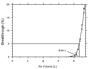
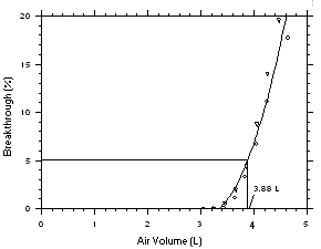
be sampled before the analyte breaks through the sampler, i.e.,
the sampler capacity is exceeded. Breakthrough is considered to
occur when the effluent from the sampler contains a
concentration of analyte that is 5% of the upstream
concentration (5% breakthrough). Testing for breakthrough was
performed by using a GC/FID to monitor the effluent from
sampling tubes, each containing 2.5 Desorption efficiency
2.5.2 The desorption efficiencies at 0.05, 0.1 and 0.2 times the target concentrations (TC) were found to be very good and are listed below. (Section 4.10)
2.5.3 Desorbed samples remain stable for at least 24 h. 2.6 Recommended air volume and sampling rate
2.6.2 For 2.6.3 When 2.7 Interferences (sampling)
2.7.3 Suspected interferences should be reported to the laboratory with submitted samples. 2.8 Safety precautions (sampling) 2.8.1 The sampling equipment should be attached to the worker in such a manner that it will not interfere with work performance or safety. 2.8.2 All safety practices that apply to the work area being sampled should be followed. 2.8.3 Protective eyewear should be worn when breaking off the ends of the glass sampling tubes. | |||||||||||||||||||||
|
3. Analytical Procedure
3.1.2 A GC column capable of separating the analyte of
interest from the desorbing solvent, internal standard and any
interferences. A 3.1.3 An electronic integrator or some other suitable means of measuring peak areas. A Waters 860 Networking Computer System and an HP GC ChemStation were used in this evaluation. 3.1.4 Two- and 3.1.5 Three-fourths milliliter autosampler vials (8-mm ×
3.1.6 A dispenser capable of delivering 4.0 mL of desorbing
solvent to prepare standards and samples. If a dispenser is
not available, a 3.2 Reagents
3.2.2 1,1,2-Trichloro-1,2,2-trifluoroethane (Freon 113), reagent grade or better. The Freon 113, distilled in glass, used in this evaluation was purchased from Burdick & Jackson Laboratories, Inc. (Muskegon, MI). 3.2.3 Carbon disulfide (CS2), reagent grade or better. The CS2, 99.9+% - low benzene, used in this evaluation was purchased from Aldrich Chemical (Milwaukee, WI). 3.2.4 A suitable internal standard, reagent grade. The benzene, 99.94%, used in this evaluation was purchased from EM Science (Gibbstown, NJ). 3.2.5 Desorbing solvent. The desorbing solvent contains 200 µL of benzene per 1 L of CS2. 3.2.6 GC grade nitrogen, air, and hydrogen. 3.3 Standard preparation
3.3.2 Bracket sample concentrations with working standard concentrations. If samples fall outside the concentration range of prepared standards, prepare and analyze additional standards or dilute the sample. 3.4 Sample preparation
3.4.2 Add 4.0 mL of desorbing solvent to each
3.4.3 Insert the 0.75-mL vial into the
3.4.4 Shake the vial vigorously by hand several times while keeping the vial horizontally during the next 60 min. This will permit the solvent inside the small vial to mix with the solvent in the larger vial. Do not use a mechanical shaker to agitate the sample. The adsorbent beads will cause the small vial to become stuck in the neck of the larger vial and the result will be inadequate desorption. 3.4.5 Transfer the sample solution to a 3.5 Analysis
3.2 An internal standard (ISTD)
calibration method is used. A calibration curve can be
constructed by plotting micrograms of analyte per sample
versus 3.6 Interferences (analytical)
3.6.2 Generally, chromatographic conditions can be altered to separate an interference from the analyte. 3.6.3 When necessary, the identity or purity of an analyte peak may be confirmed with additional analytical data. (Section 4.11) 3.7 Calculations The amount of analyte per sampler is obtained from the appropriate calibration curve in terms of micrograms per sample, uncorrected for desorption efficiency. The back tube is analyzed primarily to determine if there was any breakthrough from the front tube during sampling. If a significant amount of analyte is found on the back tube (e.g., greater than 25% of the amount found on the front tube), this fact should be reported with the sample results. If any analyte is found on the back tube, it is added to the amount on the front tube. This amount is then corrected by subtracting the total amount (if any) found on the blank. The air concentration is calculated using the following formulae.
3.8 Safety precautions (analytical)
3.8.2 Avoid skin contact and inhalation of all chemicals. 3.8.3 Wear safety glasses, gloves and a lab coat at all times while in the laboratory areas. |
|
4. Backup Data
YDL - YBR = 3(SDBR) Detection limits, in general, are defined as the amount (or concentration) of analyte that gives a response (YDL) that is significantly different [three standard deviations (SDBR)] from the background response (YBR).
The measurement of YBR and SDBR in chromatographic methods is typically inconvenient and difficult because YBR is usually extremely low. Estimates of these parameters can be made with data obtained from the analysis of a series of analytical standards or samples whose responses are in the vicinity of the background response. The regression curve obtained for a plot of instrument response versus concentration of analyte will usually be linear. Assuming SDBR and the precision of the data about curve are similar, the standard error of estimate (SEE) for the regression curve can be substituted for SDBR in the above equation. The following calculations derive a formula for DL:
At point YDL on the regression curve YDL = A(DL) + YBR where A is analytical sensitivity (slope) therefore
Substituting 3(SEE) + YBR for YDL gives
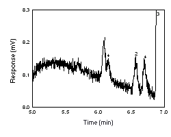
4.2 Detection limit of the analytical procedure (DLAP) The DLAP is measured as the mass of analyte actually
introduced into the chromatographic column. Ten analytical
standards were prepared in equal descending increments with the
highest standard containing 19.2 and 30.7 µg/mL of Freon 141b
and Freon 113, respectively. This is the concentration that
would produce a peak approximately 10 times the baseline noise
of a reagent blank near the elution time of the analyte. These
standards, and the reagent blank, were analyzed with the
recommended analytical parameters
| |||||||||||||||||||||||||||||||||||||||
| 4.3 Detection limit of the overall procedure (DLOP)
The DLOP is measured as mass per sample and expressed as equivalent air concentration, based on the recommended sampling parameters. Ten samplers were spiked with equal descending increments of analyte, such that the highest sampler loading was 76.9 and 123 µg/sample of Freon 141b and Freon 113, respectively. This is the amount, when spiked on a sampler, that would produce a peak approximately 10 times the baseline noise for a sample blank. These spiked samplers, plus a sample blank, were analyzed with the recommended analytical parameters, and the data obtained used to calculate the required parameters (A and SEE) for the calculation of the DLOP. For Freon 141b, the values of 4.12 and 44 were obtained for A and SEE, respectively and the DLOP was calculated to be 4.0 µg per sample (0.84 ppm or 4.0 mg/m3). For Freon 113, the values of 2.33 and 62 were obtained for A and SEE, respectively and the DLOP was calculated to be 7.2 µg per sample (0.94 ppm or 7.2 mg/m3).
4.4 Reliable quantitation limit (RQL)
The RQL for each analyte was calculated and is listed above. The recovery of the analyte near the RQL was 99.5% and 96.3% for Freon 141b and Freon 113, respectively. | ||||||||||||||||||||||||||||||||||||||||||||
| 4.5 Precision (analytical method)
The precision of the analytical procedure is measured as the pooled relative standard deviation (RSDP). Relative standard deviations are determined from six replicate injections of analyte standards at 0.5, 0.75, 1, 1.5 and 2 times the target concentration. After assuring that the RSDs satisfy the Cochran test for homogeneity at the 95% confidence level, RSDP was calculated to be 0.93% and 0.45% for Freon 141b and Freon 113, respectively.
| ||||||||||||||||||||||||||||||||||||||||||||||||||||||||||||
|
The Cochran test for homogeneity:
The critical value of the g-statistic, at the 95% confidence level, for five variances, each associated with six observations is 0.5065. The g-statistics are 0.2801 and 0.3301 for Freon 141b and Freon 113, respectively. Because the g-statistic does not exceed this value, the RSDs can be considered equal and they can be pooled (RSDP) to give an estimated RSD for the concentration range studied.
4.6 Precision (overall procedure) The precision of the overall procedure is determined from the storage data in Section 4.7. The determination of the standard error of estimate (SEER) for a regression line plotted through the graphed storage data allows the inclusion of storage time as one of the factors affecting overall precision. The SEER is similar to the standard deviation, except it is a measure of the dispersion of data about a regression line instead of about a mean. It is determined with the following equation:
An additional 5% for pump error (SP) is added to the SEER by the addition of variances to obtain the total standard error of the estimate.
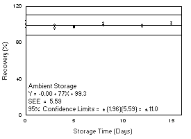
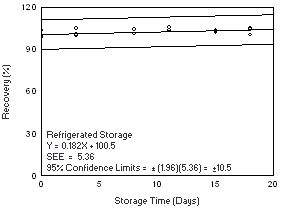
The precision at the 95% confidence level is obtained by multiplying the standard error of estimate (with pump error included) by 1.96 (the z-statistic from the standard normal distribution at the 95% confidence level). The 95% confidence intervals are drawn about their respective regression lines in the storage graphs, as shown in Figures 4.7.1.1 through 4.7.2.2. The precisions of the overall procedure and the associated figures are listed below.
|
| 4.7.1 Freon 141b
Storage samples were generated by sampling from a controlled test
atmosphere containing 3400 mg/m3 of Freon
141b, about 0.7 times the
| ||||||||||||||||||||||||||||||||||||||||||
|
4.7.2 Freon 113 Storage samples were generated by sampling from a controlled test
atmosphere containing 6700 mg/m3 of Freon
113, about 0.9 times the
| ||||||||||||||||||||||||||||||||||||||||
| 4.8 Reproducibility
Six samples for each analyte were prepared by drawing humid air
through the sampling tube for 20 min at 50 mL/min. The samplers were
then
| ||||||||||||||||||||||||||||||||||||||||||||||||||||||
|
The sampling capacity of a sampling tube containing 225 mg of
Anasorb CMS was tested by sampling from a dynamically generated test
atmosphere of Freon 141b (9560 mg/m3 or
1999 ppm) or Freon 113 (15300 mg/m3 or
1998 ppm). The samples were collected at 50 mL/min and the relative
humidity was about 75% at 25 °C. A GC with a gas sampling valve was
placed
| ||||||||||||||||||||||||||||||||||||||||||||||||||||
|
4.10 Desorption efficiency and stability of desorbed samples
The desorption efficiencies (DE) of Freon 141b were determined
by
The stability of desorbed samples was investigated by reanalyzing the target concentration samples 24 h after initial analysis. After the original analysis was performed, three vials were recapped with new septa while the remaining three retained their punctured septa. The samples vials were stored in the refrigerated sampling tray (10 °C) for the GC injector. The samples were reanalyzed with fresh standards. The average percent change was +1.6% for samples that were resealed with new septa, and - 0.3% for those that retained their punctured septa.
| |||||||||||||||||||||||||||||||||||||||||||||||||||||||||||||||||||||||
| 4.10.2 Freon 113
The desorption efficiencies (DE) of Freon 113 were determined by
| |||||||||||||||||||||||||||||||||||
|
The stability of desorbed samples was investigated by reanalyzing the target concentration samples 24 h after initial analysis. After the original analysis was performed, three vials were recapped with new septa while the remaining three retained their punctured septa. The samples vials were stored in the refrigerated sampling tray (10 °C) for the GC injector. The samples were reanalyzed with fresh standards. The average percent change was - 0.9% for samples that were resealed with new septa, and - 0.9% for those that retained their punctured septa.
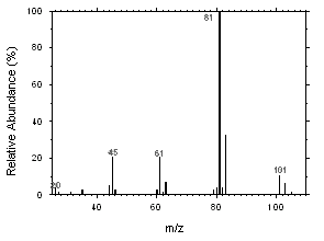
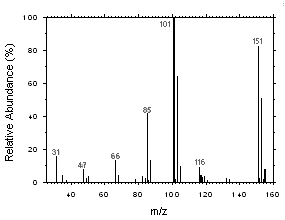
Freon 141b and Freon 113 can be easily separated and identified by GC/MS. Mass spectra were obtained from an HP5973 Mass Selective Detector interfaced to an HP6890 GC.
5. References
5.2 NIOSH Manual of Analytical
Methods, Eller, P.M., Ed, 4th ed.,
US Department of Health and Human Services, Public Health
Service, Centers for Disease Control, National Institute for
Occupational Safety and Health, Division of Physical Science and
Engineering, Cincinnati, OH, DHHS (NIOSH) Publication No.
5.3 NIOSH Manual of Analytical
Methods, Eller, P.M., Ed, 4th ed.,
US Department of Health and Human Services, Public Health
Service, Centers for Disease Control, National Institute for
Occupational Safety and Health, Division of Physical Science and
Engineering, Cincinnati, OH, DHHS (NIOSH) Publication No.
5.4 OSHA Computerized Information System Database, Chemical Sampling Information, Salt Lake Technical Center, Occupational Safety and Health Administration, Salt Lake City, UT, Sept 1998. (Back to text) 5.5 Occupational Health Guidelines for
Chemical Substances, NIOSH/OSHA, DHHS (NIOSH) Publ No.
5.6 Material Safety Data Sheet:
5.7 Documentation of the Threshold
limits Values and Biological Exposures Indices,
6th ed., American Conference of
Governmental Industrial Hygienists, Inc.: Cincinnati, OH, 1991,
Vol. III, pp. 5.8 Hileman, B.; A Chilling Battle. Chem. Eng. News, 1998, 76(31), 33-34. (Back to text) 5.9 Material Safety Data Sheet; Trichlorotrifluoroethane, DuPont Canada, Inc., Mississauga, Ontario, Jan 1998. (Back to text) | ||||||||||||||||||||||||||||||||||||||

