(METHYL ETHYL KETONE)
| Method no.: | 16 |
| Matrix: | Air |
| Target concentration: | 200 ppm (590
|
| Procedure: | Collection on silica gel, desorption with DMSO, and analysis by gas chromatography with a flame ionization detector. |
| Recommended air volume and sampling rate: |
3 L at 0.1 L/min |
| Detection limit of the overall procedure: |
1.4 ppm (4.0
|
| Reliable quantitation limit: | 1.5 ppm (4.3
|
| Standard error of estimate at the PEL: (Section 4.6.) |
5.9% |
| Special requirements: | Samples are collected on 2 silica gel tubes in series. The second tube is used as a backup for the first tube. |
| Status of method: | Evaluated method. This method has been subjected to the established evaluation procedures of the Organic Methods Evaluation Branch. |
| Date: January 1980 | Chemist: Carl J. Elskamp |
OSHA Analytical Laboratory
Salt Lake City, Utah
1. General Discussion
- 1.1. Background
- 1.1.1. History
MEK (Methyl Ethyl Ketone) samples analyzed at the OSHA laboratory have normally been collected on activated charcoal and analyzed by gas chromatography after desorption with carbon disulfide as described in NIOSH Method S3 (Ref. 5.1.) It was found by a later study that MEK was not stable on coconut shell charcoal, especially when the vapor samples were collected at high humidity and also when the samples were stored at room temperature (Ref. 5.2.). Since the OSHA laboratory analyzes a large number of MEK samples (more than 4300 MEK samples were analyzed in fiscal year 1979) and a stability problem has been established for samples collected using the NIOSH method, it was necessary to find a more suitable method of collection.
Several different solid adsorbents were tested for breakthrough.
Among those tested that gave unsatisfactory breakthrough volumes
were: Chromosorb 101, Chromosorb 102, Chromosorb 103, Chromosorb
104, Chromosorb 105, Chromosorb 106, Chromosorb 107, Chromosorb 108,
XAD-2 resin, Alumina, Tenax, Porapak P, and Chromosorb 102 coated
with 15% SP2401. These adsorbents exhibited a relatively low
capacity under the following test conditions: MEK concentration -
1176
The only solid adsorbents found suitable for collection besides coconut shell charcoal were petroleum-base charcoal (SKC Lot 104) and silica gel. These two adsorbents were evaluated according to the evaluation scheme used by the Organic Methods Evaluation Branch. The analytical procedure was essentially NIOSH Method S3 for the Lot 104 charcoal samples and an adapted method (Ref. 5.3.) using DMSO as the desorption solvent for the silica gel samples.
The silica gel collection is the recommended method of choice since samples are more stable if collected this way. Charcoal should not be used unless absolutely necessary . If charcoal is used, the samples must be refrigerated immediately after sampling and during shipment to the laboratory. Data for both procedures is included in this report. Data for the Lot 104 charcoal tube method is given in Section 4.8.
1.1.2. Toxic effects (This section is for information only and should not be taken as the basis for OSHA policy.)
MEK may be irritating to eyes, mucous membranes, and in high concentrations, narcotic. (Ref. 5.4.) MEK is similar to but more irritating than acetone. The vapor is irritating to mucous membranes and conjunctiva. No serious poisonings were reported in man except for dermatitis. (Ref. 5.5) Dermatitis can result if excessive repeated prolonged skin contact occurs. Minor skin contacts have been shown to cause no evidence of irritation. (Ref. 5.6.) MEK can be recognized at 25 ppm by its odor, which is similar to acetone but more irritating. The warning properties prevent inadvertent exposure to toxic levels. (Ref. 5.7.) The TLV was established at a level to prevent injurious effects and minimize complaints about odor and irritation. (Ref. 5.8.)
1.1.3. Operations where exposure occurs
MEK is mainly used as a solvent for formulations of nitrocellulose. (Ref. 5.9.) It is also used as a solvent in fabric coating, the manufacture of colorless synthetic resins, the manufacture of smokeless powder, the surface coating industry, the manufacture of artificial leather, the lacquer and varnish industry, pharmaceuticals and cosmetics, the manufacture of synthetic rubber, production of lubricating oils, vinyl coatings, adhesives, acrylic coatings, hardwood pulping, the manufacture of ink, and lube oil de-waxing by solvent extraction. (Ref. 5.10.)
1.1.4. Size of work population that are exposed
NIOSH estimates that over 3 million workers are potentially exposed to MEK in the United States. (Ref. 5.9.)
1.1.5. Physical Properties (Ref. 5.4. and 5.11.)
| molecular weight: | 72.10 |
| boiling point: | 79.6°C |
| color: | clear, colorless |
| vapor pressure: | 90.7 mm Hg at 25°C |
| flash point: | 35°F |
| odor: | acetone-like |
| specific gravity: | 0.805 (20/4°C) |
| lower explosive limit: | 1.8% (by volume) |
| molecular formula: | CH3COC2H5 |
| synonyms : | 2-butanone, methyl ethyl ketone, MEK, ethyl methyl ketone |
1.2. Limit defining parameters
- 1.2.1. Detection limit of the analytical procedure
The detection limit of the analytical procedure is 12.1 ng per injection. The magnitude of the detection limit is due to an interference in DMSO. (Section 4.1.)
1.2.2. Detection limit of the overall procedure
The detection limit of the overall procedure is 13.0 µ per sample
(1.5 ppm/4.3
1.2.3. Reliable quantitation limit
The reliable quantitation limit is the same as the detection limit of the overall procedure since the recovery at this level is greater than 75% and the 95% confidence limit is within ±25%. (Section 4.3.)
The reliable quantitation limit and detection limits reported in the method are based upon optimization of the instrument for the smallest possible amount of analyte. When the target concentration of an analyte is exceptionally higher than these limits, they may not be attainable at the routine operating parameters.
- 1.2.4. Sensitivity
The sensitivity of the analytical procedure over a concentration
range representing 335 to 1342
1.2.5. Desorption efficiency
The recovery of analyte from the collection medium must be 75% or greater. The average recovery over the range of 0.5 to 2 times the target concentration is 97.9%. (Section 4.5.)
1.2.6. Precision (analytical method only)
The pooled coefficient of variation obtained from replicate determinations of analytical standards at 0.5, 1 and 2 times the target concentration is 0.0061. (Section 4.4.)
1.2.7. Precision (overall procedure)
The overall procedure must provide results at the target concentration that are ±25% or better at the 95% confidence level. The precision at the 95% confidence level for the 15-day storage test is ±12.2% (Section 4.6.) This includes an additional ±5% for sampling error.
1.3. Advantages
- 1.3.1. The sampling procedure is convenient.
1.3.2. The analytical procedure is sensitive and reproducible.
1.3.3. Reanalysis of samples is possible.
1.3.4. Samples are stable, even at room temperature.
1.3.5. It may be possible to determine other compounds simultaneously .
1.3.6. Interferences can be circumvented by proper selection of GC parameters.
1.3.7. The desorption solvent (DMSO) elutes later than most solvents normally analyzed for in industrial air.
1.4. Disadvantages
- 1.4.1. The amount of sample that can be taken is limited by the
total milligrams the silica gel will adsorb before over loading.
1.4.2. The precision is limited by the reproducibility of the pressure drop across the tubes. The pumps are usually calibrated for one set of tubes only.
1.4.3. The desorption solvent (DMSO) elutes late, which increases the run time for analysis.
1.4.4. DMSO has trace contaminants that may be potential interferences under high sensitivity conditions. Under normal operating conditions, these contaminants pose no problem to analysis.
1.4.5. After repeated injections of DMSO, there is a build-up of residue formed in the collector of the detector.
2. Sampling Procedure
- 2.1. Apparatus
- 2.1.1. An approved and calibrated personal sampling pump whose
flow can be determined within ?% at the recommended flow.
2.1.2. Silica gel tubes: glass tube with both ends flame sealed, 70 mm × 6-mm i.d. containing 2 sections of 20/40 mesh silica gel separated by a 2-mm portion of urethane foam. The adsorbing section contains 150 mg of silica gel, the backup section 75 mg. A 3-mm portion of urethane foam is placed between the outlet end of the tube and the backup section. A plug of silane-treated glass wool is placed in front of the front section. The pressure drop across the tube must be less than one inch of mercury at a flow rate of 1 L/min. SKC No. 226-10 tubes or equivalent.
2.2. Reagents
None required
2.3. Sampling technique
- 2.3.1. Immediately before sampling, break open the ends of the
silica gel tubes. All tubes must be from the same lot.
2.3.2. Connect two tubes in series to the sampling pump with flexible tubing. The short sections of the silica gel tubes should be positioned nearer the sampling pump. The tube closer to the pump is used as a backup. A minimum amount of tubing is used to connect the two sampling tubes together.
2.3.3. The tubes should be placed in a vertical position during sampling to minimize channeling.
2.3.4. Air being sampled should not pass through any hose or tubing before entering the silica gel tubes.
2.3.5. Seal the separate silica gel tubes with plastic caps immediately after sampling and wrap lengthwise with an official OSHA seal (Form 21).
2.3.6. With each batch of samples, submit at least one blank tube from the same lot used for samples. This tube should be subjected to exactly the same handling as the samples (break, seal, transport) except that no air is drawn through it.
2.3.7. Transport the samples (and corresponding paperwork) to the lab for analysis.
2.3.8. If bulk samples are submitted for analysis, they should be transported in glass containers with Teflon-lined caps. These samples must not be put in the same container used for the silica gel tubes.
2.4. Breakthrough
- 2.4.1. The average 5% breakthrough volume for a single silica
gel tube containing both sections of adsorbent is 3.4 L. This value
was obtained from three separate determinations by sampling a 1174
2.4.2. The breakthrough volume is severely lowered by high relative humidity. With dry air (essentially 0% relative humidity) the breakthrough volume under the conditions described in 2.4.1. is increased to 20.3 L. Also, water will displace MEK as shown in Figure 4.7.
2.5. Desorption efficiency
- 2.5.1. The desorption efficiency, from liquid injections onto
silica gel tubes, averaged 97.9% from 0.5 to 2 times the target
concentration for a 3.0-L air sample. (Section 4.5.)
2.5.2. The desorption efficiency may vary from one laboratory to another and also from one lot of silica gel to another. Thus, it is necessary to determine the desorption efficiency for a particular lot of silica gel.
2.6. Recommended air volume and sampling rate
- 2.6.1. The recommended air volume is 3 L.
2.6.2. The recommended maximum sampling rate is 0.1 L/min.
2.7. Interferences
- 2.7.1. Besides water, it is unknown if any other compound would
severely interfere with the collection of MEK on silica gel. In
general, the presence of other compounds that have a higher affinity
for silica gel than MEK does (i.e., higher polarity than MEK) would
decrease the breakthrough volume for MEK.
2.7.2. Suspected interferences should be listed on the sample data sheets.
2.8. Safety precautions
- 2.8.1. Attach the sampling equipment on the employee so that it
does not interfere with work performance.
2.8.2. Wear safety glasses when breaking the ends of the sampling tubes.
2.8.3. If possible, place the sampling tubes in a holder so the sharp end is not exposed while sampling.
3. Analytical procedure
- 3.1. Apparatus
- 3.1.1. A GC equipped with a flame ionization detector.
3.1.2. A GC column capable of separating MEK and an internal standard from any interferences and DMSO. The column used for validation studies was: 10-ft × l/8-in. stainless steel, 20% SP2401, 0.1% CW1500 on 100/120 Supelcoport.
3.1.3. An electronic integrator or some other suitable method of measuring peak areas.
3.1.4. Two-milliliter vials with Teflon-lined caps.
3.1.5. Microliter syringes, 10-µ or other convenient sizes for preparing standards and 1-µ for sample injections.
3.1.6. Pipets for dispensing DMSO. A Glenco 1-mL dispenser is adequate and convenient.
3.1.7. Volumetric flasks, 5-mL and other convenient sizes for preparing standards.
3.2. Reagents
- 3.2.1. 2-Butanone (MEK), reagent grade.
3.2.2. Dimethyl sulfoxide (DMSO), chromatographic grade.
3.2.3. A reagent grade internal standard, such as ethyl benzene.
3.2.4. Desorbing reagent, 1 µ internal standard/mL DMSO.
3.2.5. Helium, hydrogen, and air, purified GC grade.
3.3. Sample preparation
- 3.3.1. The combined contents (front and back section) of each
sample tube are transferred to a 2-mL vial.
3.3.2. Each sample is desorbed with 1.0 mL of desorbing reagent.
3.3.3. The vials are sealed immediately and the samples are desorbed for 30 min with occasional shaking.
3.4. Standard preparation
- 3.4.1. Standards are prepared by diluting pure MEK with the
desorbing reagent.
3.4.2. One microliter of MEK per milliliter of desorbing reagent is equivalent to 91.0 ppm for a 3-L air sample desorbed with 1 mL of desorbing reagent. This amount is uncorrected for desorption efficiency. The corrected amount is 92.95 (91.00/0.979).
3.5. Analysis
- 3.5.1. GC conditions
| zone temperatures (°) | flow rates (mL/min) | ||||
| column: | 140 | nitrogen: | 25 | ||
| injector: | 200 | hydrogen: | 22 | ||
| detector: | 300 | air: | 240 | ||
| injection size: | 1 µ | ||||
| elution time: | 1.3 min | ||||
| chromatogram: | Figure 3.5.1. | ||||
3.5.2. Peak areas are measured by an integrator or other suitable means.
3.5.3. An internal standard procedure is used. The integrator is calibrated to report results in ppm for a 3-L air sample after correction for desorption efficiency.
3.6. Interferences
- 3.6.1. Any compound having the same general retention time of
MEK or the internal standard used is an interference. Possible
interferences are listed on the sample data sheets. GC parameters
should be chosen so these interferences will pose no problems.
3.6.2. GC parameters may be changed to circumvent any other interferences.
3.6.3. There are usually trace contaminants in DMSO. At normal operating parameters, they are insignificant.
3.6.4. Retention time data on a single column is not considered proof of chemical identity. Samples over the PEL should be confirmed by GC/MS or other suitable means.
3.7. Calculations
Since the integrator is programmed to report results in ppm for a 3-L air sample (corrected for desorption efficiency), the following calculation is used to correct results to the actual air volume sampled:
| ppm MEK = | (ppm on report) (3)
(liters of air sampled) |
3.8. Safety precautions
- 3.8.1. All work done with the solvents (preparation of
standards, desorption of samples, etc.) should be done in a hood.
3.8.2. Avoid skin contact with any of the solvents.
3.8.3. Wear safety glasses at all times.
4. Backup Data
- 4.1. Detection limit data
The detection limit was determined by injecting 1 µ of a 12.1 µ/mL
standard of MEK in DMSO. The detection limit of the analytical
procedure is taken to be 12.1 ng per injection. This is equivalent to
1.4 ppm (4.0
4.2. Detection limit of the overall procedure
The detection limit of the overall procedure was determined from the following desorption data. This data is presented graphically in Figures 4.2.1. and 4.2.2.
Desorption Data Used to Determine the
Detection Limit of the Overall Procedure
|
| ||||||
| µ/sample | 3528 | 1764 | 882 | 402.5 | 201.3 | 12.1 |
|
| ||||||
| µ | 3474.7 | 1734.4 | 854.0 | 385.2 | 186.8 | 11.59 |
| recovered | 3471.2 | 1738.2 | 848.3 | 389.6 | 192.0 | 11.14 |
| 3509.2 | 1717.3 | 832.9 | 390.4 | 193.7 | 10.68 | |
| 3495.2 | 1738.2 | 854.0 | ||||
| 3475.1 | 1730.1 | 854.1 | ||||
| 1731.7 | 858.2 | |||||
|
| ||||||
4.3. Reliable quantitation limit
The reliable quantitation limit is the same as the detection limit of the overall procedure. The data of Table 4.3. shows that the requirements of at least 75% recovery and a precision (1.96 SD) ?% or better are met.
Recovery and Precision for
the Reliable Quantitation Limit
|
| |||
| µ/sample | 13 | ||
|
| |||
| % recovered | 95.8 | ||
| 88.3 | SD = 3.8 | ||
| 92.1 | 1.96(SD) = 7.4 | ||
|
| |||
4.4. Sensitivity and precision data (analytical method only)
The following data, which was obtained from the repeated analysis of three analytical standards representing 0.5, 1, and 2 times the target concentration, was used to determine the calibration curve and precision of the analytical method. The calibration curve is shown in Figure 4.4.
Sensitivity and Precision
|
| |||
| × target conc. | 0.5× | 1× | 2× |
| mg/mL | 1.006 | 2.012 | 4.025 |
|
| |||
| area counts | 146007 | 287364 | 565884 |
| 144168 | 286358 | 565567 | |
| 142940 | 285360 | 566004 | |
| 144050 | 283879 | 564308 | |
| 143825 | 282414 | 563603 | |
| 144138 | 281906 | 567043 | |
| 144188 | 284547 | 565401 | |
| SD | 1002.0 | 2183.9 | 1244.8 |
| CV | 0.00695 | 0.00768 | 0.00220 |
|
| |||
4.5. Desorption efficiency
The desorption efficiency was determined by spiking MEK onto silica gel tubes and desorbing with DMSO. Recoveries were done at 0.5, 1, and 2 times the target concentration for the recommended air volume.
Desorption Efficiency
|
| |||
| × target conc. | 0.5× | l× | 2× |
|
| |||
| desorption | 96.8 | 98.3 | 98.5 |
| efficiency, | 96.2 | 98.5 | 98.5 |
| % | 96.4 | 97.4 | 98.4 |
| 96.8 | 98.5 | 99.5 | |
| 96.8 | 98.0 | 99.1 | |
| 97.3 | 98.2 | 98.5 | |
| 96.7 | 98.2 | 98.8 | |
|
| |||
4.6. Storage data
Thirty-six samples were collected from a test atmosphere containing
531
Storage Tests
|
| ||||||
| storage time | % recovery | |||||
| (days) | (refrigerated) | (ambient) | ||||
|
| ||||||
| 0 | 94.3 | 97.6 | 95.0 | 94.3 | 97.6 | 95.0 |
| 0 | 93.6 | 95.9 | 99.3 | 93.6 | 95.9 | 99.3 |
| 3 | 99.0 | 99.9 | 96.2 | 98.5 | 95.4 | 97.5 |
| 6 | 105.5 | 97.3 | 101.2 | 101.1 | 107.7 | 97.9 |
| 9 | 99.9 | 98.5 | 98.4 | 99.0 | 96.0 | 99.1 |
| 12 | 98.0 | 97.3 | 96.8 | 97.8 | 96.5 | 96.9 |
| 15 | 99.2 | 96.9 | 98.5 | 99.8 | 95.5 | 96.0 |
|
| ||||||
4.7. Sampler capacity
Breakthrough studies were done at 1174
Breakthrough Data
|
| |||
| min for 5% | liters of | mg of MEK | |
| breakthrough | air sampled | collected | |
|
| |||
| 38.5 | 3.54 | 4.16 | |
| 37.0 | 3.40 | 4.00 | |
| 34.5 | 3.17 | 3.73 | |
| 36.7 | 3.37 | 3.96 | |
|
| |||
An additional sample was tested for breakthrough under the above conditions except dry air was used. The breakthrough volume was increased to 20.3 L or 23.8 mg of MEK.
4.8. Collection of MEK on lot 104 (petroleum-base) charcoal
The collection of MEK on Lot 104 charcoal was also evaluated. The procedure is the same as the silica gel method except the collection volume is increased to 5 L, only one tube is used for collection, and carbon disulfide is used as the desorption solvent.
- 4.8.1. Detection limit (analytical procedure only)
The detection limit of the analytical procedure is 0.32 ng per injection. (Figure 4.8.1.)
4.8.2. Sensitivity and precision data (analytical procedure only)
The following data, which was obtained from the repeated analysis
of three analytical standards representing 322 to 1610
Sensitivity and Precision
|
| |||
| mg/mL | 1.61 | 3.22 | 8.05 |
|
| |||
| 281844 | 556085 | 1365890 | |
| 228542 | 568482 | 1388810 | |
| 281451 | 557165 | 1400030 | |
| 280060 | 567225 | 1395220 | |
| 282081 | 570739 | 1372920 | |
| 280368 | 563104 | 1386640 | |
| 281391 | 563800 | 1384920 | |
| SD | 982.6 | 6096.4 | 13104.5 |
| CV | 0.00349 | 0.0108 | 0.00946 |
|
| |||
4.8.3. Desorption efficiency
The desorption efficiencies were determined by injecting MEK onto the front sections of charcoal tubes at concentrations equivalent to 0.5, 1, and 2 times the target concentration for the recommended air volume of 5 L.
Desorption Efficiency
|
| |||
| × target conc. | 0.5× | l× | 2× |
|
| |||
| desorption | 93.0 | 95.8 | 95.0 |
| efficiency, | 93.3 | 96.5 | 95.6 |
| % | 92.9 | 95.3 | 95.9 |
| 92.6 | 95.5 | 95.3 | |
| 93.0 | 95.5 | 95.6 | |
| 93.4 | 95.3 | 94.6 | |
| 93.0 | 95.6 | 95.3 | |
|
| |||
4.8.4. Storage data
Thirty-six samples were collected from a test atmosphere
containing 588
Storage Tests
|
| ||||||
| storage time | % recovery | |||||
| (days) | (refrigerated) | (ambient) | ||||
|
| ||||||
| 0 | 85.3 | 84.4 | 84.5 | 85.3 | 84.4 | 84.5 |
| 0 | 84.8 | 85.9 | 86.4 | 84.8 | 85.9 | 86.4 |
| 3 | 75.4 | 77.3 | 77.5 | 68.2 | 68.6 | 66.7 |
| 6 | 71.4 | 70.6 | 71.7 | 60.7 | 60.8 | 59.2 |
| 10 | 68.6 | 68.8 | 68.2 | 54.6 | 56.6 | 54.9 |
| 12 | 68.5 | 67.2 | 66.9 | 53.6 | 53.9 | 54.4 |
| 16 | 66.5 | 66.4 | 66.8 | 50.6 | 51.9 | 52.4 |
|
| ||||||
4.8.5. Sampler capacity
A breakthrough study was done on the front section of Lot 104
charcoal. The MEK vapor concentration was 1176
Breakthrough Data
|
| |||
| min for 5% | liters of | mg of MEK | |
| breakthrough | air sampled | collected | |
|
| |||
| 56.5 | 6.65 | 6.64 | |
| 60.2 | 6.02 | 7.08 | |
| 56.8 | 5.68 | 6.68 | |
| 57.8 | 5.78 | 6.80 | |
|
| |||
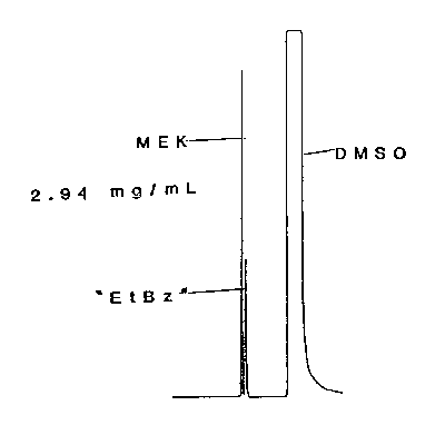
Figure 3.5.1. Chromatogram of an MEK standard.
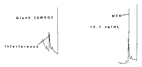
Figure 4.1. Chromatograms for the detection limit.

Figure 4.2.1. Detection limit of the overall procedure.

Figure 4.2.2. Detection limit of the overall procedure.
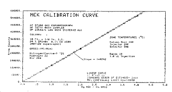
Figure 4.4. Calibration curve.
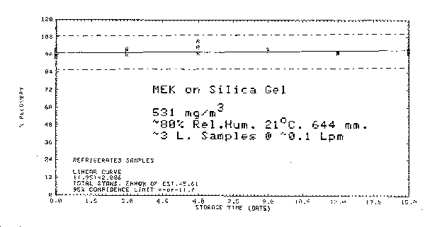
Figure 4.6..1. Refrigerated storage.

Figure 4.6.2. Ambient storage.

Figure 4.6.3. Refrigerated versus ambient storage.
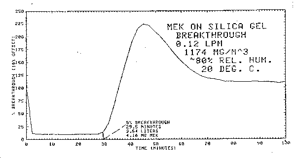
Figure 4.7. Breakthrough curve.
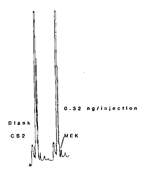
Figure 4.8.1. Chromatograms for the detection limit.
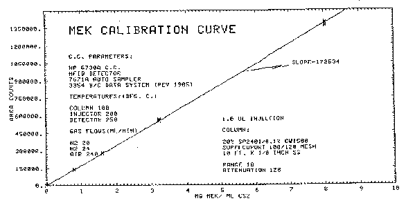
Figure 4.8.2. Calibration curve.
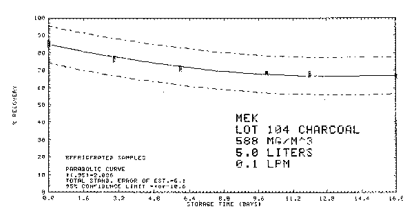
Figure 4.8.4.1. Refrigerated storage.
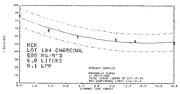
Figure 4.8.4.2. Ambient storage.
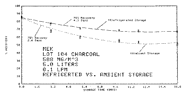
Figure 4.8.4.3. Refrigerated versus ambient storage.

Figure 4.8.5. Breakthrough curve.
5. References
- 5.1. "NIOSH Manual of Analytical Methods", U.S. Department of
Health, Education, and Welfare, Public Health Service, Center for
Disease Control, National Institute for Occupational Safety and
Health, Second Edition, Vol. 2., Method S3.
5.2. "An Investigative Report on the Stability of Selected Ketones on Activated Charcoal," by Carl J. Elskamp, OSHA Analytical Laboratory, Salt Lake City, Utah, Unpublished, 1979.
5.3. Feldstein, M.; Balestrieri, S.; Levaggi, D.A., AIHA J. 1967, 28, 381-385.
5.4. "Merck Index", published by Ed., Ninth Edition, p. 792.
5.5. Gosselin, R.E., ed., "Clinical Fourth Edition, Set II, 124.
5.6. Patty, "Industrial Hygiene and Toxicology". Second Edition, Bolume 2, p. 1732.
5.7. Rowe, V.K., and Wolf, M.A.: "Ketones". In Fassett, D.W., and Irish, D.D. (Eds.): Toxicology Vol. 2. In Patty, F.A. (ed.): "Industrial Hygiene and Toxicology". ed. 2, pp. 1731-1733. New York: Interscience, 1963. In Proctor, N.H. and Hughes, J.P., (eds.): "Chemical Hazards of the Workplace", p. 344, J. B. Lippincott Co., 1978.
5.8. A.C.G.I.H.: 2-Butanone (Methyl Ethyl Ketone). "Documentation of the TLVs for Substances in Workroom Air"., ed. 3, p. 29. Cincinnati, 1976. In Procter, N.H. and Hughes, J.P., (eds.): "Chemical Hazards of the Workplace". p. 344. J.B. Lippincott Co., 1978.
5.9. "NIOSH Criteria for a Recommended Standard: Occupational Exposure to Ketones"., U.S. Department of Health, Education, and Welfare, PHS/CDC/NIOSH, pp. 23-24, June, 1978.
5.10. Toxicology Data Bank (on line data base), National Library of Medicine, Methyl Ethyl Ketone Manufacturing Data, 1979.
5.11. American Industrial Hygiene Association, "Hygienic Guide Series - Methyl Ethyl Ketone (Butanone)", April, 1964.